UML Diagrams for Java Developers
The Unified Modeling Language is a graphical notation for modeling systems and conveying User software requirements. All developers must understand this notation before starting programming.
UML is not only pretty pictures. Instead, they communicate the software design decisions to programmers.
Use case
As entrepreneurs, we usually pay for costly advertisements to promote our products. We can create a little application to make our ads, promote them as printed flyers, and reduce our investments in ads.
Every developer can abstract the main components from a user requirement differently. Having a standard UML notation helps to eliminate ambiguities about the requirements from the beginning. I want to show you how to translate business requirements into technical solutions with this use case.
User requirement
Given a text message, a URL link, and an image, build a service that automates the composition of flyer design, including the image, text, and the QR code for the link in a PDF file with an A4 format divided into one, two, four or eight parts ready to print.
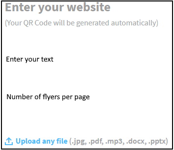
From the user requirement, we can realize that we need a task to create a QR code, a job to manipulate elements inside an image, and a task to create a PDF file.
We can implement our code or reuse external libraries as dependencies, but the following figure shows the desired result, whatever the implementation approach is chosen.

Why do we model?
- We build models to understand better the system we are developing.
- Models document the design decisions we have made.
- Models allow an open discussion in the development team before starting programming.
- It speeds up the implementation stage because potential technical issues are discussed during the design stage.
Visualizing software architecture - design proposal
The C4 model enables software development teams to describe and communicate software design decisions, similar to Google maps zooming in and out of an area of interest.
These areas of interest in the software are:
Context -> Containers -> Components -> Code - UML Notation
Context diagram
A system context diagram shows the big picture. This diagram shows actors and software systems rather than technologies. For our use case, it says that building a new web application will achieve the user requirement.

Container diagram
The container diagram shows how the responsibilities are distributed in different execution units - containers.
We need a Form on the front end and an API application on the back end for our web application.

Component diagram
As system analysts, we delegate responsibilities to software elements called components or services that execute sub-tasks with specific technologies to achieve the user software requirements. Read the Single Responsibility Principle.
The API application interacts with the user requests. Then, delegates the following subtasks to different services.
- Generate a QR Code based on the URL link achieved by the QR Service.
- Merge the previous QR Code, text message, and image in a final image design performed by the Image Service.
- Build a PDF file that includes the last design image achieved by the PDF Service.
The API application returns the final image design in a PDF file to the user.

It’s better to include a new service called FlyerComposerService between the API application and the three services. It facilitates the migration task if you want to adopt a microservices architecture.
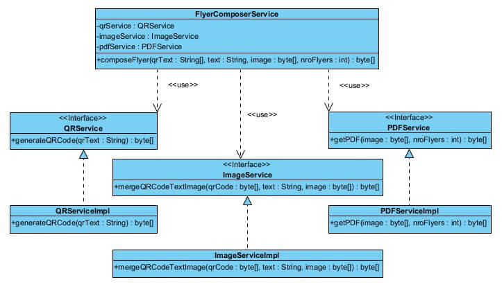
The FlyerComposerService class is responsible for orchestrating all calls to these three last services.
UML Class Diagrams
A class is a template for creating objects providing initial values for state (attributes) and behavior (operations). Each attribute has a type. Each operation has a signature.
From the figure above:
- The first compartment describes the class name.
- The second compartment describes the attributes with its visibility, private(-) or public(+), and their types.
- The third compartment describes the operations and their return types.
The following code snippet shows how these compartments are translated into code.
1
2
3
4
5
6
7
8
9
10
11
12
13
14
15
public class FlyerComposerService {

  private QRService qrService;
  private ImageService imageService;
  private PDFService pdfService;

  public byte[] composeFlyer(String[] qrText,
    String text,
    byte[] image,
    int nroFlyers) {

    //code omitted for brevity
  }

}
Relationships between classes
UML conveys how a class is related to other classes. Let’s see the kind of relationships that matter to our design.
Dependency
Dependency is a relationship used to show that some class requires or depends on another class or interface. In other words, some class provides (supplier) particular functionalities that others require (client).
At the FlyerComposerService class above, we can see how is declared the dependencies as member variables.
Realization
Realization is a relationship where one class realizes or implements the specification defined in another class (usually an interface).
Defining and creating interfaces is an excellent approach to building software to is extendable. Read the Open-Closed Principle.
The implemented code reflects the intent of the UML designer.
Using UML diagrams in Java projects is an excellent tool for effective team communication. The following figure conveys the Class diagram.
For example, we can see how the QRService interface is implemented into code.
1
2
3
public interface QRService {
  byte[] generateQRCode(String qrText) throws Exception;
}
In addition, we can see how the QRServiceImpl class is implemented into code
1
2
3
4
5
6
7
public class QRServiceImpl implements QRService {
  @Override
  public byte[] generateQRCode(String qrText) throws Exception {

  //code omitted for brevity
  }
}
Relationships among Objects
Objects contribute to the behavior of a system by collaborating with one another. An object communicates with another object to use the results of operations provided by that object.
Association, Aggregation, and Composition are terms that represent relationships among objects. They are fundamental concepts of Object Oriented Programming.
Association
An association draws a solid line connecting two classes. It could be named by a verb (using role names) that reflects the business problem domain we are modeling. The following diagram shows two classes that need to communicate with each other.

Aggregation
Aggregation is a particular association type representing a has-a relationship and is displayed as a solid line with an unfilled diamond at the association end.
A child class object can exist without the parent class object. In the following diagram, if you delete the Buyer class (parent), the Supplier class (child) still exists.

Composition
Composition is a particular type of aggregation where parts are destroyed when the whole is destroyed. The relationship is displayed as a solid line with a filled diamond at the association end.
A child class object cannot exist without the parent class object. In the following diagram, if you delete the Order class (parent), the Address class (child) is also deleted.

Applications of Aggregation/Composition diagrams
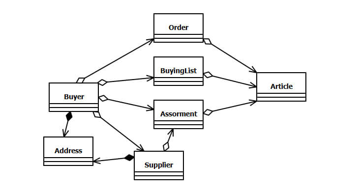
We can use aggregation/composition diagrams to design API endpoints. For example, the following figure shows the relationships among different business model objects.
To get orders placed by a specific buyer:
1
GET /api/v2/buyers/{buyerId}/orders
To get all articles included in an assortment that belongs to a specific buyer:
1
GET /api/v2/buyers/{buyerId}/assortments/{assortmentId}/articles
Conclusions
- UML convey how to build the software without ambiguities, e.g., build first an interface instead of a class.
- Modeling through UML yields an understanding of a system.
- An explicit UML class diagram facilitates communication between developers.
- UML diagrams can be used as a documentation tool for Java development teams.
We will see how to implement every Spring Boot service in the following articles, so follow me!


